Tuesday, August 4, 2015

LackRack - A Cheap Living Room 19" Rack

I needed space so I decided to expand my desk. While I was entertaining several ideas about how to best do that, I also happened to measure some of my existing furniture. My first discovery was that some compartments in my old Ikea bookshelf have dimensions that are suitable (more or less) for 19" equipment. My second discovery was that the very same is true for the Ikea LACK tables. And my third, and quickest, discovery was to find out that I am not the first person to discover that: Like for most things on the internet, there already exists a community around the use of LACK tables as 19" racks, and the official name for this purpose is ( - wait for it - ) LackRack. Apparently first seen on an IT related event, LackRack quickly gathered a small fanbase in the DIY server/network and music scenes, due to is cheap price, availability and flexibility.

However, for my LackRack  I pictured several features that differed from the standard solutions yone finds on the net: a total height of about 90cm would very well fit to my desk space, wheels could add spontaneous flexibility in my gear arrangements, the 19" part also should be as flexible as possible, a part (besides the 19" section) dedicated for storing cables would be a nice bonus. On these grounds, I decided for a two story solution: The upper part would be comprised of the already mentioned LACK table (7,99 Eur), the base would be a LACK side table on castors which I found in mint condition for almost half the price (15,- Euro) on classifieds.


Slight inconvenience with the LACK tables, but I guess that with the cheap price, is that the legs are mainly built from cardboard and hence are hollow except the top and bottom 5 cm. Since I wanted to fill my rack top to bottom and therefore the screws will need to be able to support some weight, screwing the modules directly into the table's legs consequently was not an option. However, I did not like that idea in the first place, since it also decreases any later possibilities to rearrange modules (at least I assum that the screw holes wear off over time). Instead, I opted for continuous rack rails which can be fastened in the solid sections of the table's legs, and which allow me to freely manoeuvre my gear around at a later time. Adam Hall had some in his portfolio (10,- Eur), that perfectly matched my needs, are used with standard M6 screws, and were quickly sawn to an appropriate length of 38 cm:


For optical reasons, I painted the rail's inner sides black, and then put all parts together:


A very flexible, 90,5 cm high, two compartment 19" rack for 30,- Eur, that might not be suitable to be carried from live act to live act, but does not need to hide in the living room.


Continue reading on how a central power supply with lights complemented the new rack.


LackRack - Power and Lights with a modded T.Racks VM-100


This time it will be all about adding a power strip and lights to the LackRack.


A quick word in the beginning:
This blog post is not intended as a tutorial, I wrote it for pure documentation purposes only. 
Do not try this if you do not posses the required technical knowledge and skills. 
The voltages we are dealing with are life-threatening, and improper handling/assembly can further cause heavy damage to property including the risk of fire.


Having said that, I wanted the power supply for my rack to serve as a power strip and to provide a single on/off switch for all the gear. Rack-mountabilitiy would be considered a big plus, and optional light would just be the icing on the cake.


While there are several commercial products that satisfy these needs, constructing a rack out of cheap parts, and then spending a fortune on a reference power conditioner just felt wrong. Furthermore, electricity is absolutely stable where I live, so a simple 19" power distribution strip would do the job without the necessity of a true power conditioner.


Roaming on classifieds again, I found a T.Racks VM-100 that fulfilled my requirements and met the price range I had in mind. The T.Racks VM-100 is basically exactly what I have described above: it is a 19" power strip that bears eight IEC power connectors on its back, has two dimmable lights that can be extended/retracted, has a central power switch with a 10A fuse, plus it sports an additional fancy looking LED volt meter. While I can imagine that the voltmeter can be quite handy in on-the-road conditions, in my home it really just looks fancy. Unfortunately it looks fancy all the time, because it displays the available voltage even when the power switch is turned off. Again, this might be great for gigs, but turned out to be an annoyance in my living room.


Opening the VM-100 quickly revealed the reason for this behaviour:


T.Racks VM-100


As seen in the zoomed picture, the white and black cables (which are the ones that drive the voltmeter) are connected pre-switch:


Pre-switch voltmeter


However, a quick rewiring connected the voltmeter post-switch and post-fuse, and readily solved that issue: the device is now pitch-black when turned off, and only unfolds its full fanciness when being switched on.


Post-switch voltmeter


Not being sure if 10A will be enough to drive all equipment (at the time being they are sufficient), it would be great to transform the volt meter into an ampere-meter, but that is a mod for another time.

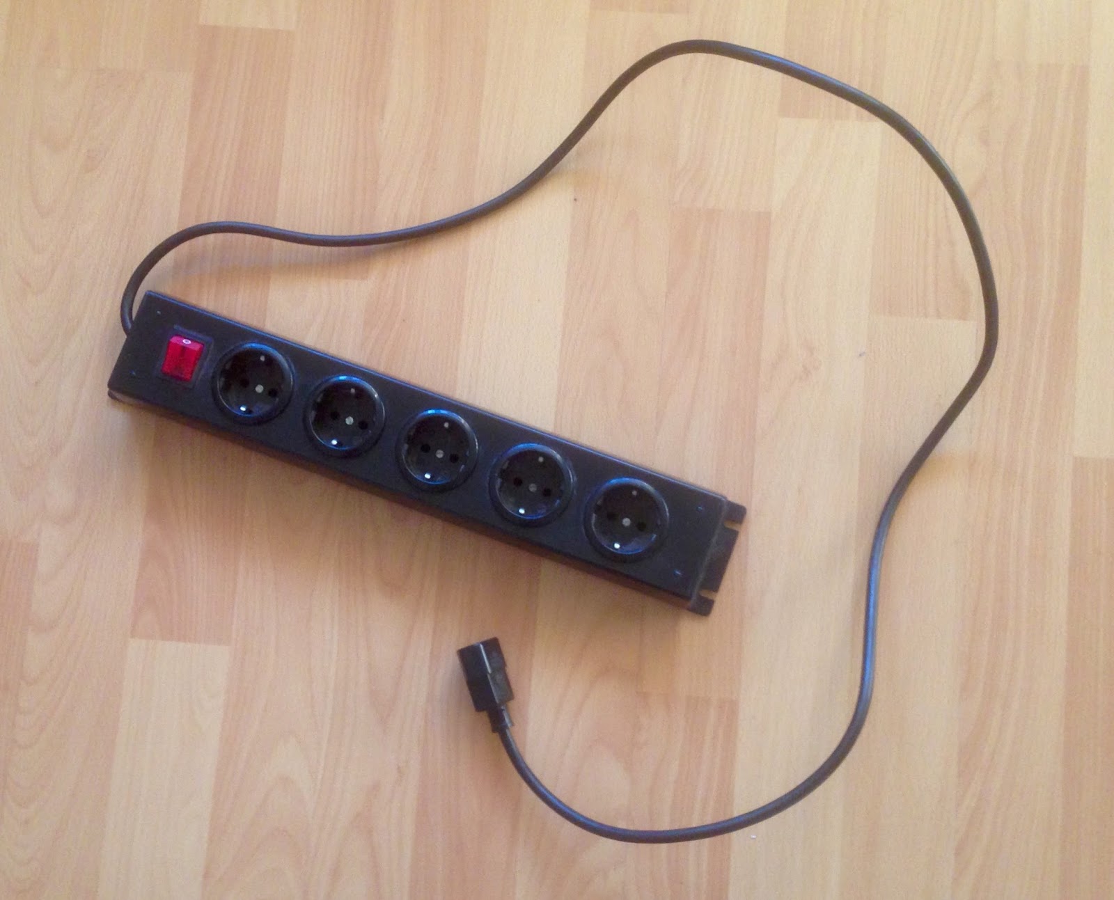
Anyway, since a lot of my stuff has wall adapters, I also changed a standard power strip to an IEC version and connected it to the T.Racks:


Schuko version
IEC version


And here is the LackRack in its full glory now:


Hint: a glimpse of one of my next projects is already seen underneath the VM-100 :)


Thursday, July 23, 2015

Rhythm Wolf - Individual Drums Outs


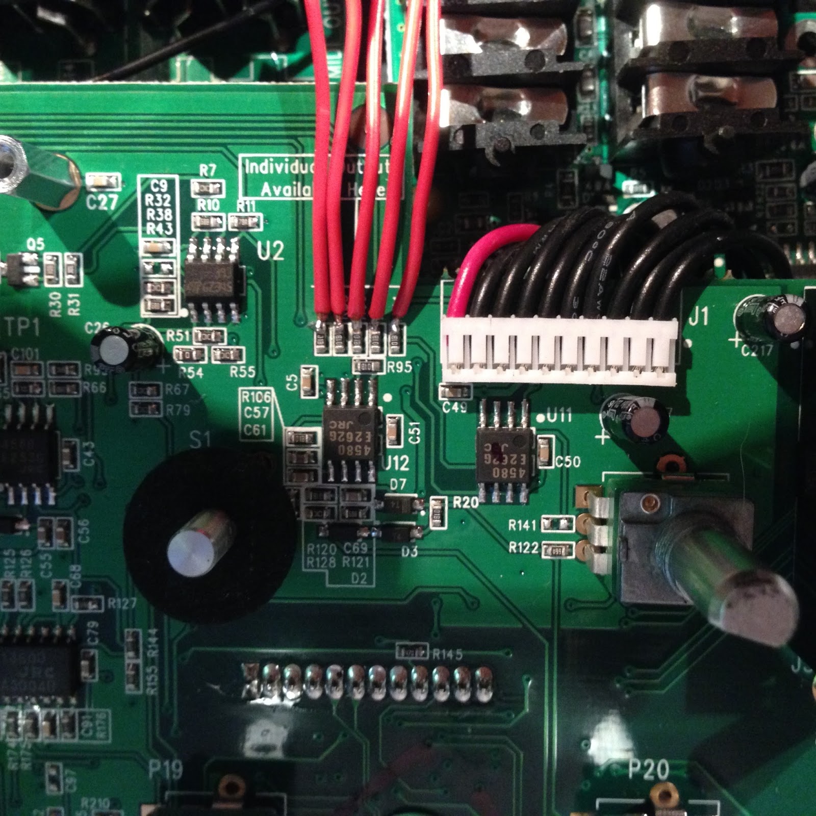
I got asked by a friend if I could help him modifying his Akai Rhythm Wolf for individual outputs. After opening the little box, it became quickly clear that Akai was nice enough to label five resistors with "Individual Outputs Available Here". Not knowing about the signal levels, etc, it seemed worth to just give it a try and to simply wire them to mini jacks.

For this, I solderd five (red) cables to the upper part of the resistors.


The respective resistors are located left of the TSR jacks, suggesting that the levels get mixed here afterwards.


Quickly measuring the voltages passing through those connections, it became clear that none of them is ground. However, ground can be picked up almost everywhere on the board, and I soldered it to the sleeves of a all (mono) mini jacks. Similarly, the red wires got soldered to the tips.
Initial trials indicated that the signal level was very much sufficient for my friends amplifier/mixer, and also that the corresponding sounds did not get ablated in the main mix. So after drilling small holes into the backside of the case and attaching the jacks there the mod was done :)


Wednesday, July 22, 2015

Home Automation - Farewell Old Friend

Everything has to end at some point. Here and now, my very first project ends.
The one that made me familiar with µcontrollers.
The one that brought me to electronics.
The one that initiated me as a tinkerer.


HardWareHub


Actually, that is not true - it is the other way around. I started the project because I wanted to do something with µcontrollers and wanted to dive into the world of electronics. What I was missing at that point was a project; a purpose for my tries. That was HardWareHub.

While it is not strictly about sound creation, it is connected with the purpose of this blog in the wider sense and deserves a comment here: HardWareHub was a home automation system. When I started playing music in iTunes, I wanted my amplifier to automatically turn on, switch to the correct input source and to turn the bass down if it is late at night. Similarly, if I received a phone call, the volume faded out and iTunes went on pause. If the TV got turned on, the same actions happened, in case music was playing, but the amplifier switched to the TV source.

It worked quite well for a couple of years, but like many projects without a defined goal, it happened to be in a constant state of changes. At one point I got distracted by other projects and it happened to be left with some functionality temporarily turned off. Consequently, I happened to use it less and less lately and I want to officially focus on more current projects now. When I decluttered some cables in my living room yesterday, I removed the Arduino, the heart of HardWareHub, to give it a new purpose.


Some details for those of you interested in similar projects. HardWareHub consisted of three parts:
  • an Arduino managing the hardware side and communicating with my living rooms appliances by mimicking the IR commands of their remotes
  • an applescript continuously running as a demon on my computer (which never gets turned off anyway) communicating with the Arduino and assessing states of iTunes, Plex, router (Fritzbox), browser (yes, it also worked with youtube), brightness of my computer screen, etc.
  • two javascript widgets to serve as GUIs
last but not least, however I would not consider this a real "part", there was a USB controlled power outlet (Gembird SIS-PM) to switch lights and some devices on/off.


Implemented features included:
  • full control over a stereo amplifier through IR commands
  • full control over a projected using similar commands
  • responsive to their native remotes
  • responsive to my own IR commands
  • control over room lights through USB controllable outlets
  • auto mount of my NAS on startup
  • iTunes control through applescript
  • PLEX control through HTML commands
  • "knowing" if youtube is playing by measuring the performance burden of the web browser
  • responding to phone calls (ingoing and outgoing) though an api of the router (Fritzbox)
  • evaluating the time of the day and adjusting volume and bass/treble settings
  • action based GUI (e.g.. Movie mode turns on the stereo and the projector, switches to the correct input sources, starts PLEX, turns off iTunes, turns the lights off, ...
  • device based GUI for individual access to all features
Widget to control the individual devices


Good bye, it was fun and I have learned a lot thanks to you - now it is time to move on...


Thursday, July 2, 2015

Celebration

I am very happy to announce that my code to receive and send MIDI Time Code messages and a yet unpublished function to send Real Time messages was just added to the official Teensy core libraries.


Celebrating:


Monday, June 22, 2015

Receiving MIDI Time Codes over USB with the Teensy

Due to a request of a reader of my blog, I elaborated on my extensions for the Teensy 3.x usb_midi library by adding support for callback functions to receive MIDI Time Code (MTC) messages. To fully understand the code, I recommend also reading my post for generating the MTC.

Briefly, the library files where we need to add the missing functions are located (on Mac OS X) in Contents/Java/hardware/teensy/avr/cores/teensy3/. This folder can be found by right-clicking on your Arduino application and then selecting Show Package Contents from the drop down menu.

You can either download the modified files from my GitHub repository and copy them to above folder, or you can modify the files yourself by following the following simple instructions:

Open usb_midi.h and search for "#ifdef __cplusplus". Add the following code one line above that:

Now search for "private:" and add this code right before it:

You are almost done. Save and close the file, and open usb_midi.c instead. Search for "// Maximum number of transmit packets to ..." and add this line above:

As a last step, search for "return 0; } #endif // F_CPU" (they might be distributed over multiple lines) and add these lines of code before the "return 0;"

And voilá, you can now receive MTC messages over USB and evaluate them with callback functions.
Your callback function will receive the MTC as a word parameter. An example sketch showing how to do the decoding is included in the repository...


Tuesday, June 16, 2015

Monotribe fun


Opinions about the Monotribe are quite controversial. While many like the sound this little device can produce, its lack of midi, 2nd oscillator, etc, are considered a huge draw back by others. Flanked by the Monotron series on the low budget end and with the Volca series having more functionality, the Monotribe appears obsolete and can be tough to integrate into your workflow. However, I got an offer for one that I could not decline - and I love the little thing. Its sound is (except being prone for clicks on note on and off events) raw analog and rich, while not missing a certain level of aggressiveness either.

Further, many of the points of criticism can be readily addressed by slight hardware modifications. These are largely facilitated by labelled soldering pads that Korg graciously put on the pcb. In addition, Midi functionality can be added without the necessity of physically changing the Monotribe, by using a serial connector present in the device and by using Midi commands and messages that are already integrated in all the official firmware releases. Consequently, several commercially available Midi kits from third-parties are at hand, however, these are often overpriced, considering only costs for materials, and many modifications can be implemented with only few and simple steps for a fraction of the price of a kit.

In this context, a modification scene has formed around the Monotribe with a plethora of mods being well described and published online. This information is often dispersed among several sources and I will summarise some of them here while implementing them in my own Monotribe,

Since I would like to have both, Midi DIN connections as well as over USB, I decided to use the Teensy microprocessor again to manage all communication and serve as a bridge between Monotribe, DIN and USB. This approach has also the advantage that there will be quite some processing power available for additional modifications of the synthesizer...


My first implementation is quite crude and demonstrates only basic capabilities: while the Teensy already takes care of the USB Midi communication I further added a small OLED display and a joystick. The display, so far, shows which note is currently played, either through Midi or on the Monotribe's ribbon keyboard, indicates the active drum sounds with icons (not shown in the picture), and visualises the position of the joystick - which in turn controlles LFO frequency and range.