Sunday, January 3, 2016

MIDIfication

My projects are regularly based on the Teensy and Arduino/Genuino development platforms. While the former natively supports MIDI over USB, I often have the need for DIN support. The following instructions connect DIN input and outputs to you Teensy (all) and Arduino (Zero, Uno, Due, Mega, Leonardo, Yun, Nano, Micro, Mini) boards.

The circuit in general is very simple and can be soldered by beginners as well. For testing purposes, a prototyping board can also be used:


MIDI Out

Connecting a DIN output to the Teensy is straight forward. Although the Teensy runs at 3.3V, while the MIDI standard specifies 5V operation, virtually all MIDI devices function with a 3.3V connection without any problem. To have DIN MIDI output, connect pin 2 of the output DIN to ground (Teensy pin GND), pin 4 through a 220 Ohm resistor to 3.3V (on the Teensy), and pin 5 gets connected to the Teensy's TX (Teensy pin 1):

  • MIDI OUT pin 2 - Teensy GND
  • MIDI OUT pin 4 - 220 Ohm resistor - Teensy 3.3V
  • MIDI OUT pin 5 - Teensy pin 1 (TX)


MIDI In

The DIN input is a bit more elaborate. Here, we isolate our circuit from the circuit of the MIDI partner (which itself will be isolated from all input, that is why our output can be so simple). We do this with an opto-isolator, and a good one for this purpose is the 6N137 for its sharp transient signals and 3.3V suitability. Also it is cheap and available from numerous manufacturers.  Pin 4 of the input DIN is connected through a 220 Ohm resistor to pin 2 of the 6N137 (the spot marks pin 1, we use the one directly next to that), and DIN pin 5 goes to 6N137 pin 3. Similarly, pin 5 on the 6N137 is connected to the GND pin on the Teensy. Pin 6 goes to RX (pin 0) on the Teensy, and 8 on the 6N137 goes to 3.3V as well as RX (the latter through a 5.6 kOhm resistor). If you want to be extra secure, you can stabilise the 6N137s power lines by putting a 100n capacitor (ceramic is fine) between them (pin 5 and pin 8) as close to the chip as possible. To further protect your circuit from reverse polarity (someone swapping + and - on the MIDI cable), add a 1N4148 diode between pin 2 and 3 of the 6N137. While the orientation of all resistors and capacitors used here does not matter, the diode has to be put in a specific direction: the side with the solid black line points to pin 2:

  • MIDI IN pin 4 - 220 Ohm resistor - 6N137 pin 2
  • MIDI IN pin 5 - 6N137 pin 3
  • 6N137 pin 2 - 1N4148 diode - 6N137 pin 3 (the black bar on the diode points to pin 2)
  • 6N137 pin 5 - Teensy GND
  • 6N137 pin 6 - Teensy pin 0 (RX)
  • 6N137 pin 8 - Teensy 3.3V
  • 6N137 pin 8 - 5.6K resistor - Teensy pin 0 (RX)
  • 6N137 pin 5 - 100nF capacitor - 6N137 pin 8

Software

The standard Arduino MIDI library can be used to access the DINs. Actually, please use the standard MIDI library. The one that comes with the Teensyduino environment is based on a much older version and will not function correctly with my code (it is initialised differently).

If you start from scratch on a Mac (it is basically the same in Windows, but I happen to have a Mac):
  • Get the Arduino IDE from here and install it
  • Get the MIDI library from here and install it (described here)
  • Get the software you want to install from my GiHub repository
  • Open the firmware in the Arduino IDE and edit the features listed in the beginning of the file
  • Use the USB cable to connect the Arduino to your computer
  • Choose your Arduino board and its connected USB port in the Tools menu of the IDE
  • Press the Upload button
  • Voilà

Prototyping

In the above picture, the connections are as following (always from left to right): top left - DIN input pins 5, 4; bottom left - DIN output pins 2, 4, 5; bottom right - Teensy pins 1, 0. Also don't forget to connect + to 3.3V on the Teensy, and - to GND. For the interested among you, the schematics are the following:


Tuesday, December 22, 2015

Monotribe - Removing clicking sounds


I really like the sound of my Monotribe and so far have not experienced the clicking sounds so many people complain about as really noticeable. This changed when I needed to run it through a reverb...

The clicks and pops are caused by the phase of the oscillator when a note is triggered (in the envelopes reverse saw and square setting). The following schematic visualises that:


When a note is triggered while, by chance, the VCO is at TO or T2 of its wave cycle (I know that the Monotribe has only square, saw and triangle wave shapes, but it really is the same as for the sine shown here), the resulting sound will smoothly "start". In contrast, at any other point in time, the generated sound will jump-start at the current point in the wave cycle, resulting in a noticeable click or pop sound. This can be avoided by either re-triggering the VCO with every note played (the Monotribe does not do that), or starting each note at a low volume and only turning it up after the pop has occurred (a.k.a. the attack phase of an envelope). Since the Monotribe's envelope, at least in its square and reverse saw setting, is really fast, it gives a very snappy tone - but with clicks and pops. A good electronic description on how and why this happens in the Monotribe is well described by Mark Madel in this YouTube video.

Based on Mark's and Snyder80's suggestions in the  30+ page Monotribe modification thread on Muff Wiggler, adding a 1 µF WIMA foil capacitor (any above 16V will be fine) to the base of Q24 and GND softens the envelope and gets completely rid of the clicking problem of the Monotribe.


As seen in the photos, I attached wires to the corresponding points on the pcb instead of directly soldering the capacitor. This not only enabled me to easily play around with different capacitor values (but Snyder80 was absolutely right by using a 1µF capacitor), but also allowed for putting a switch between the capacitor and the Q24 transfer, to turn the mod off when a most snappy envelope is desired.


As a side note: The above mentioned Monotribe modification thread on Muff Wiggler is a must read for anyone aiming to improve their Monotribe. While also being fun to read, the highly informative thread contains many good ideas and solutions to common Monotribe problems and often renders it unnecessary to reinvent the wheel.


Sunday, December 6, 2015

Pimp my Drum Machine

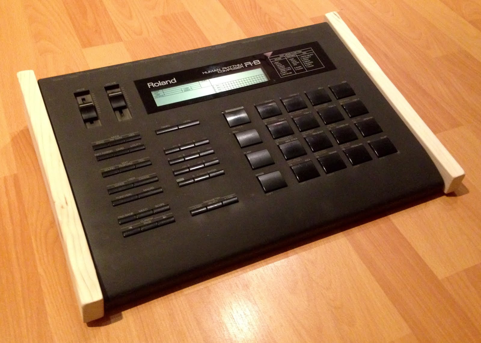
A very quick one for in-between: 30min to optically upgraded my Roland R8 with wooden sides.

The Roland R8 Human Rhythm Composer does not need any introduction. "One of the very best drum machines ever", was a game changer upon its release in 1988 and dominated the electronic music production in the 90ies. Almost 30 years later, mine was still in a pretty good condition, but was due for a little optical make over.

I got a wooden plank at the local hardware store and, after roughly cutting it into two similar sized parts, schematically indicated the R8's dimensions on it. A circular saw quickly manifested my drawings in shapes (upper part), a rasp gave them a smooth surface and edges, while sticking rubber feet to them completed the whole process.


Last but not least, the sides needed to be fixed to the devices body. Since the R8 has withstood the marks of time quite well, I did not want to apply permanent changes to its case and therefore did not see drilling holes into it as an option. so I decided for glueing. Among the available glues, I opted for hot-melt adhesives as they are pretty stable, but can also be removed without leaving residues. After a total of about 60min, my R8 was successfully pimped :)


Friday, November 13, 2015

Play the Kaossilator Pro with standard MIDI controllers (solder-free tweak)


I very much enjoy the intuitive play on the Korg Kaossilator Pro+. However, while I experience the touch pad to be great for implementing rhythms, drone sounds and simple patterns, I often don't hit the notes accurately enough during more complex loops, and often considerably disturb my harmonies. Consequently, every now and then, I would like to play individual parts with a standard USB MIDI controller or sequencer.

Since the Kaossilator is designed to be played via the touch pad, also the MIDI implementation is tailored around corresponding commands. In practice: my MIDI keyboard sends a note on command when I hit a key, while the Kaossilator expects a control change # 74 (to signal that the touch pad was pressed), and then control changes # 12 and # 13 (to define the X and Y coordinates on the pad) to play a sound. I experience this as quite annoying, but it is easy to fix without extensively trying to reconfigure the MIDI controller's behaviour:

In contrast of most of my other projects, this hack is optimised for easy and solder-free implementation. For this reason, together with its straight forward MIDI implementation, I again designed this project around the Teensy development board. While this could be implemented cheaper with a variety of other boards and some simple circuitry, the Teensy LC (which is available for around 12 USD/EUR) will only need a micro-usb to usb cable and my Kontroller firmware.

Since the hack is designed for stock boards, it is very suitable for the absolute DIY beginner and therefore I also guide through the installation steps of the software required to put the Kontroller (not overly creative, but quite a suitable name for this hack) firmware on the Teensy board.

Assuming you have a Mac (it is the very same on other systems, however, the software installation routines are slightly different and I cannot confirm the exact names of menu points etc.), and that this is your first contact with the Arduino world, download the Arduino software here.

After installing (by moving the Arduino icon into your application folder), download the Teensyduino extension and install it via its installer. During this process, you will have to indicate where you have just put the Arduino IDE (hint: it is in your application folder), as well as point out which Teensy libraries you want to have pre-installed (for this purpose, it is save to not install any. Particularly do not install the MIDI library, it is based on an old version. If you want the MIDI library, like for MIDI DINs etc, get it from here).

Now it is time to get the actual Kontroller firmware from my GitHub section. Download it, and open it in the Arduino IDE. You can change the setting to your liking as described in the beginning of the file. Just add or remove "#" characters at the beginning of each line to inactivate or activate the setting, respectively. Configureable options include:
  • enable/disable modulation of the X-axis (the note's pitch) by your keyboard's pitch wheel
  • enable/disable notes velocity to define the Y-axis (often a filter or delay)
  • enable/disable a control change # (which can be freely chosen) to define the Y-axis
  • enable/disable aftertouch to modify the Y-axis value
  • enable/disable indication of played notes on the built-in LED of the Teensy (Why not?)

Connect your Teensy board and, in the Tools menu, select Board: "Teensy LC" and USB type: "MIDI". Then press Upload in the Sketch menu.

And done! Kind of. The Kaossilator gives us two options to communicate with it via MIDI: USB and DIN. Since implementation of the latter requires construction of a (very basic) circuit, I neglected this route in order to provide an assembly-free solution. However, implementing MIDI DINs is really easy and straight forward, so feel free to contact me if you want instructions for that as well.

Focusing on USB, unfortunately this communication was designed for a USB master to interact with USB slaves. That is also why you typically cannot directly connect your USB MIDI keyboard to your instruments, but have to go through a master, i.e. your computer. Having said that, this means you will have all your devices (Kaossilator, Kontroller, Keyboard/Sequencer) connected to a computer for this to work. And you need to configure your computer to pass the information from your USB MIDI device through the Teensy Kontroller to your Kaossilator. On a mac, a free software to do so is MIDI patchbay


MIDI Patchbay: use the Teensy as a man-in-the-middle usb device

Despite being quite aged, it does the job well. Downlaod it from the provided link, move the app to the applications folder and start it. The first patch will manage the connection between your MIDI device and the Kontroller. MIDI input should reflect the name of your device, while MIDI output should say "Teensy MIDI". Apply your corresponding Channel settings and, under Note, allow all notes. Then click the "Add Patch" button to make the Kontroller to Kaossilator connection. Here, the MIDI input is "Teensy MIDI" while the output should be "KAOSSILATOR PRO+ SOUND", while and the MIDI Channels have to be configured to your Kaossilator's settings. 

And done! This time for real.


A quick note for fruitful experimentation: Kontroller translates notes into coordinates on the touch pad's XY-axis of your Kaossilator Pro (+). This means that the scale, set on the Kaossilator, is respected and therefore does not necessarily reflect the pressed key's pitch. Similarly, the octave range of the Kaossilator will further modulate the notes played. While this can be quite fun as well, a one-to-one mapping can be achieved by setting the octave range of you Kaossilator to full.

Friday, October 23, 2015

Alesis 3630 Compressor Mod

I have been a bit quiet lately due to travels and too many things going on. Being back home and having some projects in a publishable state, here is the next part of my 19" rack series...

While searching for an affordable all-purpose hardware compressor, I naturally came accross the Alesis 3630. Naturally, since, according to Alesis, this "has become the most popular dynamic processor ever made". Similarly, according to Daft Punk, this little box gave the signature sound to their Homework and Discovery albums. After continueing to read about it, it quickly became clear that, together with its price, these are almost the only positive things that can be found about this compressor. Most people seem to agree that it's best usage is as a doorstop, and even the one Daft Punk used repeatedly was not the original, but a modified version. So let's modify it...

The modifications implemented here summarise the ones suggested on Icarus' post on Sound on Sound and Smallbutfine on groupdiy, which seem to replicate the original Buta mods, but also include the opinions and suggestions of several other people. Thanks to all of you!


Location of all relevant components on a Rev. D board (Click to enlarge)


Opening the Alesis 3630 is straight forward, and although the potentiometer knobs sit tightly on their shafts, they can be removed with a bit of gently controlled pressure. After disassembling the unit, the two pcbs unfold and can be separate for easier handling. Since the component's labels are printed underneath them on the one-sided boards, I made a visual overview of all changes on my Rev. D board. If your board has a different revision number, just slightly bend the components and try too peak underneath to identify the labels. Good light helps a lot on this!

Among the first things suggested for upgrading, is beefing up the components of the power supply section to give the unit a bit more headroom power-whise. For this, we replace the four big capacitors with better components and swap the four diodes with fast switching alternatives:


- Power -


Quantity New component Position Old component
2 220µF/35V Electrolytic cap C2, C3 ?
2 2200µF/25V Electrolytic cap C4, C5 ?
2 10 µF Audio grade electrolytic cap C6, C7 10 µF
4 UF4001 Diode D1, D2, D3, D4 1N400x


Next, we turn our attention to the op-amps and VCAs (Voltage Controlled Amplifier) that are responsible for the compressor's gain and thus play an important role Alesis' sound character. Several OP-Amps work equally fine in technical terms, but make a significant difference from an audible point of view. Judging which one is best depends on personal taste and the purpose of your compressor and trying to solve that question by simply reading about the different sound characteristics gets you very quickly into highly subjective, sometimes esoteric, terrain. However, for my trials I got a pair of MC33079P, which are supposed to sound very surgically clean, as well as some LME49740, which have a more musical character. Other OP-Amps that work well, but I have not tried myself, include the LT1359 (not sure about the sound), TL074 or TL084 (supposed to be darker, grittier), OPA4227 (smooth and musical) and OPA404 (very clean and quiet).


- Input -


Quantity New component Position Old component
2 MC33079P DIP-14 Quad OP-Amp U2, U6 TL084 or LF347
2 100 kOhm metal film resistor R12, R54 100 kOhm
2 1.69 kOhm metal film resistor R14, R56 1 kOhm
2 2.2 kOhm metal film resistor R13, R55 2.2 kOhm
2 6.2 kOhm metal film resistor R15, R57 6.2 kOhm
2 150 pF silver mica C12, C30 150 pF


All changes to the VCA (voltage controlled amplifier), level and knee sections consist of replacing passive parts only, so here we go:


- VCA -


Quantity New component Position Old component
2 2180BL08-U VCA IC U3, U7 2150
2 2.2 kOhm metal film resistor R42, R72 2.2 kOhm
2 6.2 kOhm metal film resistor R41, R73 6.2 kOhm
4 240 kOhm metal film resistor R27, R69, R208, R211 150 kOhm
4 20 kOhm metal film resistor R22, R23, R64 ,R65 22 kOhm
2 470 Ohm metal film resistor R26, R68 470 Ohm
2 100 Ohm metal film resistor R29, R71 100 Ohm
4 33 Ohm metal film resistor R79, R102, R209, R212 33 Ohm
2 5.1 kOhm metal film resistor R25, R67 5.1 kOhm
2 10 µF audio grade elko C43, C55 10 µF
2 22 pF metal film capacitor C15, C32 50 pF
Remove - resistor R28, R70 ?


- Level -


Quantity New component Position Old component
2 2.2 mOhm metal film resistor R10, R52 1 mOhm
2 10 kOhm metal film resistor R8, R50 10 kOhm
2 22 µF audio grade elko C11, C29 22 µF
2 10 µF audio grade elko C16, C33 0.22 µF
Remove - capacitor C42, C56 ?


- Knee -


Quantity New component Position Old component
2 5.6 kOhm metal film resistor R83, R106 1 kOhm
2 6.8 kOhm metal film resistor R17, R59 3 kOhm


Many people complain about how the mere presents of the gate circuits negatively affect the 3630's sound. The easy solution is to disconnect the gate by cutting the bridges marked in the picture with yellow circles. However, in general, I am not a friend of ultimate loss-of-function approaches, so I decided to replace the bridges with switches. Since I the front plate of the compressor is rather populated, and its rear is little accessible in a rack, I opted to replace the threshold potentiometers with switchable ones. Measuring the original potentiometers, they are 10k with their taper range somewhere between a linear and a log scale. Seeing it as an advantage to have finer control on the lower end of the scale, I ended up opting for logarithmic potentiometers as replacements. The integrated switch makes their body larger and I had to desolder and bend two capacitors on the LED board (marked with a pink circle) to gain the necessary space in the re-assembled box. Also, the pins of my replacement ones did not fit into the pcb holes, so I had to used small wires as adapters.

As a last upgrade, it is suggested to connect all input/output grounds with heavy gauge copper wire. These (thick, brown), as well as some of the wires used to connect the switchable potentiometers (thinner, orange), are well visible on my finished unit:


So how does it sound now? While it would be nice to have an original model at hand to compare it to, the 3630 has a nice musical character now. My first impression is very good and the mods seem very worth doing...


PS:
Some people also suggest to replace the side chain op-amp. I did not implement this, since I am fine with the side chain as it is. However, if anybody has experience with this modification please say a few words in the comment section about your experience and which replacement op-amp you have used.


- Side chain -


QuantityNew componentPurposePosition
1?Quad OP-AmpSide chainUx


Tuesday, August 4, 2015

LackRack - A Cheap Living Room 19" Rack

I needed space so I decided to expand my desk. While I was entertaining several ideas about how to best do that, I also happened to measure some of my existing furniture. My first discovery was that some compartments in my old Ikea bookshelf have dimensions that are suitable (more or less) for 19" equipment. My second discovery was that the very same is true for the Ikea LACK tables. And my third, and quickest, discovery was to find out that I am not the first person to discover that: Like for most things on the internet, there already exists a community around the use of LACK tables as 19" racks, and the official name for this purpose is ( - wait for it - ) LackRack. Apparently first seen on an IT related event, LackRack quickly gathered a small fanbase in the DIY server/network and music scenes, due to is cheap price, availability and flexibility.

However, for my LackRack  I pictured several features that differed from the standard solutions yone finds on the net: a total height of about 90cm would very well fit to my desk space, wheels could add spontaneous flexibility in my gear arrangements, the 19" part also should be as flexible as possible, a part (besides the 19" section) dedicated for storing cables would be a nice bonus. On these grounds, I decided for a two story solution: The upper part would be comprised of the already mentioned LACK table (7,99 Eur), the base would be a LACK side table on castors which I found in mint condition for almost half the price (15,- Euro) on classifieds.


Slight inconvenience with the LACK tables, but I guess that with the cheap price, is that the legs are mainly built from cardboard and hence are hollow except the top and bottom 5 cm. Since I wanted to fill my rack top to bottom and therefore the screws will need to be able to support some weight, screwing the modules directly into the table's legs consequently was not an option. However, I did not like that idea in the first place, since it also decreases any later possibilities to rearrange modules (at least I assum that the screw holes wear off over time). Instead, I opted for continuous rack rails which can be fastened in the solid sections of the table's legs, and which allow me to freely manoeuvre my gear around at a later time. Adam Hall had some in his portfolio (10,- Eur), that perfectly matched my needs, are used with standard M6 screws, and were quickly sawn to an appropriate length of 38 cm:


For optical reasons, I painted the rail's inner sides black, and then put all parts together:


A very flexible, 90,5 cm high, two compartment 19" rack for 30,- Eur, that might not be suitable to be carried from live act to live act, but does not need to hide in the living room.


Continue reading on how a central power supply with lights complemented the new rack.


LackRack - Power and Lights with a modded T.Racks VM-100


This time it will be all about adding a power strip and lights to the LackRack.


A quick word in the beginning:
This blog post is not intended as a tutorial, I wrote it for pure documentation purposes only. 
Do not try this if you do not posses the required technical knowledge and skills. 
The voltages we are dealing with are life-threatening, and improper handling/assembly can further cause heavy damage to property including the risk of fire.


Having said that, I wanted the power supply for my rack to serve as a power strip and to provide a single on/off switch for all the gear. Rack-mountabilitiy would be considered a big plus, and optional light would just be the icing on the cake.


While there are several commercial products that satisfy these needs, constructing a rack out of cheap parts, and then spending a fortune on a reference power conditioner just felt wrong. Furthermore, electricity is absolutely stable where I live, so a simple 19" power distribution strip would do the job without the necessity of a true power conditioner.


Roaming on classifieds again, I found a T.Racks VM-100 that fulfilled my requirements and met the price range I had in mind. The T.Racks VM-100 is basically exactly what I have described above: it is a 19" power strip that bears eight IEC power connectors on its back, has two dimmable lights that can be extended/retracted, has a central power switch with a 10A fuse, plus it sports an additional fancy looking LED volt meter. While I can imagine that the voltmeter can be quite handy in on-the-road conditions, in my home it really just looks fancy. Unfortunately it looks fancy all the time, because it displays the available voltage even when the power switch is turned off. Again, this might be great for gigs, but turned out to be an annoyance in my living room.


Opening the VM-100 quickly revealed the reason for this behaviour:


T.Racks VM-100


As seen in the zoomed picture, the white and black cables (which are the ones that drive the voltmeter) are connected pre-switch:


Pre-switch voltmeter


However, a quick rewiring connected the voltmeter post-switch and post-fuse, and readily solved that issue: the device is now pitch-black when turned off, and only unfolds its full fanciness when being switched on.


Post-switch voltmeter


Not being sure if 10A will be enough to drive all equipment (at the time being they are sufficient), it would be great to transform the volt meter into an ampere-meter, but that is a mod for another time.

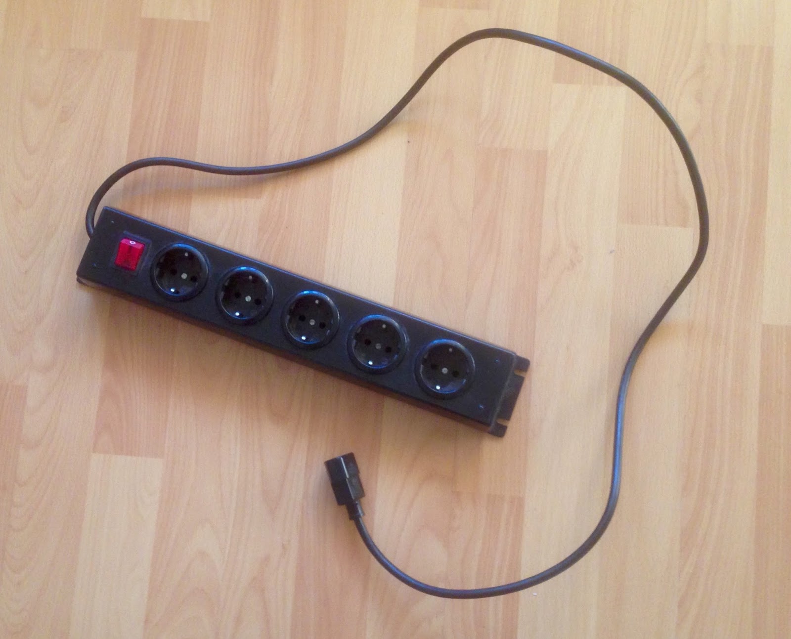
Anyway, since a lot of my stuff has wall adapters, I also changed a standard power strip to an IEC version and connected it to the T.Racks:


Schuko version
IEC version


And here is the LackRack in its full glory now:


Hint: a glimpse of one of my next projects is already seen underneath the VM-100 :)